Switched Reluctance Motor (SRM)
Construction
Last
Updated: 6/15/07
Baselined
prototype.
This
motor was made from two single phase induction motors I got from
salvage. They were chopped up and machined to make the stator stack
which was then put into the aluminum housing. The rotor was
constructed using a microwave oven transformer core. I cut out a
section of the core and had the material drilled and pressed onto the
shaft and then machined to form the rotor stack. Since
this motor is fixed in size and topology, I have built the motor
parts with close tolerances to try and compensate for the size and
material quality limitations.
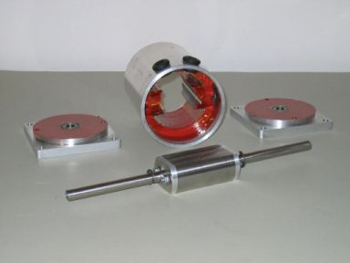
The
stator, end plates, and rotor are shown here and the motor is
disassembled to show the parts that make up the SRM motor. This is an
earlier picture before the stator was wound. The outside diameter of
the motor is 3.5 inches and the rotor diameter is 1.78 inches with
an air gap of 0.005” between each rotor and stator pole. The
shaft is grooved for “C” clips which keep the rotor
centered in the motor. I will probably need to use a beefier bearing
on the sprocket side of the motor when I put it on the kart.
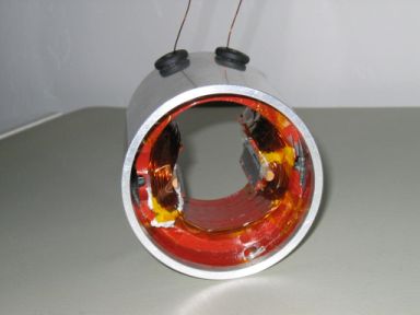
 The
red colored areas are insulation coating using transformer insulation
varnish. I applied additional insulation around the stator poles
using Kapton tape. The stator stack and housing are electrically
connected for grounding and the resistance from stator pole face to
housing is 0.4 ohms. The “sticks” on the stator poles are
there to help hold the windings in place and are permanently attached
to the poles.
The
red colored areas are insulation coating using transformer insulation
varnish. I applied additional insulation around the stator poles
using Kapton tape. The stator stack and housing are electrically
connected for grounding and the resistance from stator pole face to
housing is 0.4 ohms. The “sticks” on the stator poles are
there to help hold the windings in place and are permanently attached
to the poles.
Below
is a picture of the wound stator. It is wound using the 22GA magnet
wire and I adjusted the number of turns to get an inductance of 28mH
with rotor in aligned position and 5mH in the unaligned position. The
resistance of the windings is 1.5 ohms.
 I
first wound the stator using 20GA magnet wire to get reduced winding
resistance. I got the first stator pole half wound when the “sticks”
broke and I had to remove and replace them with the larger and
stronger wood posts epoxied in place. After getting as much 20GA wire
on both stator poles as possible, the aligned inductance was only
3mH. This was too low and I re-wound the stator with the 22GA wire.
I
first wound the stator using 20GA magnet wire to get reduced winding
resistance. I got the first stator pole half wound when the “sticks”
broke and I had to remove and replace them with the larger and
stronger wood posts epoxied in place. After getting as much 20GA wire
on both stator poles as possible, the aligned inductance was only
3mH. This was too low and I re-wound the stator with the 22GA wire.
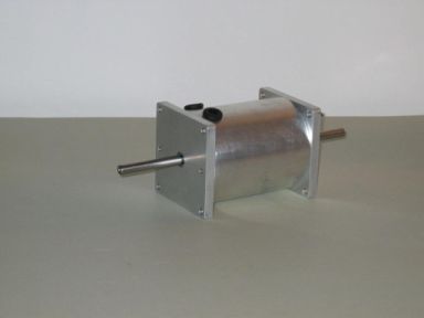 Here
is the motor assembled. The rotor turns freely with no binding even
with the relatively tight tolerances.The two rubber grommets on top
are were the high voltage leads come out of the motor. I made the
rotor shaft long on both ends so that either side can be used.
The centrifugal clutch will be
mounted on the side opposite the high voltage leads.
Here
is the motor assembled. The rotor turns freely with no binding even
with the relatively tight tolerances.The two rubber grommets on top
are were the high voltage leads come out of the motor. I made the
rotor shaft long on both ends so that either side can be used.
The centrifugal clutch will be
mounted on the side opposite the high voltage leads.
Using
the equations for magnetic circuits and switched reluctance motor
design to determine number of turns per pole and flux density yielded
results that varied by a factor of 10. I believe the reason the
design equations do not give expected results is that they factor out
or assume small non-linearities in the energizing and de-energizing
of the phase windings and my system works mostly in the non-linear
region (di/dt and dB/dt) during the power stroke.
If
you have Javascript enabled you can use the button below, else use
the back button in your browser.