High Efficiency SRM Controller
The series resonant driver concept was adapted to work in a conventional SRM controller circuit topology with constant input voltage. This new controller circuit is very similar to the stock Ametek controller that came with the motor. The new circuit uses the similar topology as in the Ametek controller, but differs in method of current sensing and control and uses a basic DC link boost capacitor. The Ametek controller used PWM combined with low side current sensing, and a DC link boost consisting of two capacitors and a diode network to cause the capacitors to charge in series and discharge in parallel.
The motor is coupled to the alternator by a multi-ribbed belt drive with a 4:1 pulley ratio (4 rotations of the motor shaft to 1 rotation of the alternator shaft). The system is designed to operate the motor at 20K rpm. The alternator is connected to a 12V motorcycle battery to excite the alternator and the output of the alternator is used to power a 1500W inverter for 120VAC, 60Hz, single phase output power. The input to the motor is 120VAC, 60Hz, single phase power. A switch is connected in series to the battery positive lead so the battery can be disconnected (or switched off) when the alternator is up and running.
At this time, the power to the motor is from a 120VAC wall outlet, and a power strip is connected to the inverter output. This allows me to easily add power loads to the inverter output (like incandescent light bulbs) and monitor the change in current going into the motor (with a current clamp meter). In its present form, a load of 100W causes the motor input current to increase by only 24W!! To make the systems self-sustaining, I need to resolve make two changes:
The controller is more efficient at low to mid rpm. With the 4:1 pulley ratio, the lower motor rpm is too slow to run the alternator, so I need to change the pulley ratio to 1:1 to allow the alternator to run at same rpm as the motor (about 5K – 8K rpm).
The controller circuit is cooled by a forced air cooling fan mounted to the motor shaft. Running the motor at lower rpm means less air flow for cooling. So I'll need to add an external cooling fan.
Per problem 1. above, the new controller is more efficient at high rpm than conventional controllers at high rpm, but it is more efficient at low rpm than at high rpm. The greater rate of change of the flux linkage at high rpm creates greater back emf which makes it more difficult to store energy in the phase windings.
Additionally, the new controller circuit design can be used to drive high brightness LEDs. For example, the circuit can drive a HB LED with average forward current of 1A, and the current from the battery is only 500mA. I will build a demo circuit in the near future.
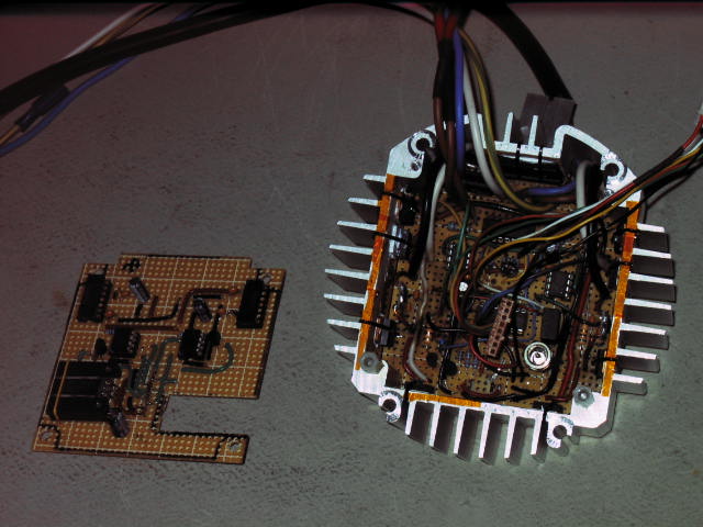
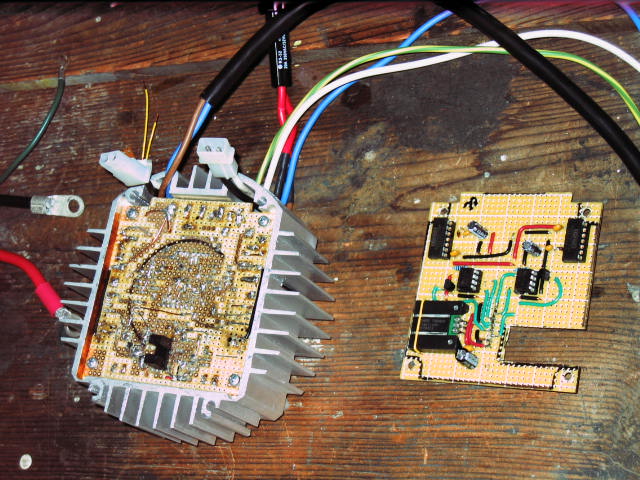
Here are some quick pictures of the system.
Pictures above: top side of controller circuit in aluminum heat sink/chassis on the left, and the bottom side of controller on the right showing the optical sensor. The small board to the side is a driver for the high side IGBTs.

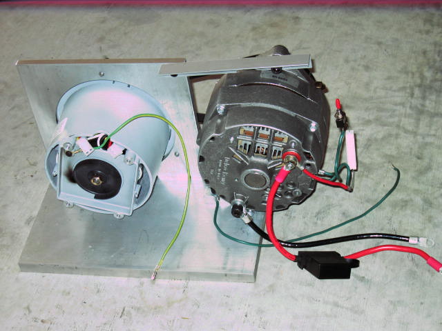
Pictures above: these pictures show the motor and alternator assembly. The left shows the belt drive setup, and the right is the back side showing the optical interrupter on the motor and the electrical connections to the alternator.
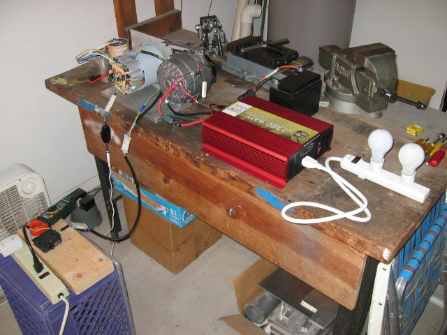
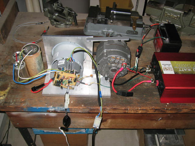
Pictures above: here is the system connected up on the workbench. After making the changes discussed to solve the two problems, the system should be able to run with the input power to the motor connected to the output of the inverter. The battery will be used to start the system