Magnetic Circuits
The magnetic circuits discussed
here use permanent magnets, however, I consider them to be in the
electromagnetic category because the circuits can use electromagnets,
permanent magnets, or a combination of both. The purpose of these
circuits is to demonstrate concepts in manipulating magnetic fields
in order to control the attractive and repulsive forces and to
justify further exploitation of the concepts.
Magnetic
field shorting repulsive circuit:
In this circuit, two permanent
magnets are arranged to repel each other with one magnet mounted on a
stationary platform and the second magnet is mounted on the end of a
linearly movable shaft or piston. A movable sleeve of high magnetic
permeable material (mild steel in this example) is used to “short
circuit” the opposing magnetic fields which allows the piston
to be pushed close to the stationary magnet with much less force than
without the sleeve. With careful positioning of the sleeve, it can be
pulled back with relatively little force to allow the magnets to be
“open circuited” and repel each other with greater force.
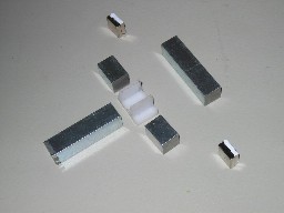
Below are pictures of a test
fixture I build to try out this concept. The platform and the piston
(the black pieces) are made out of delrin plastic.
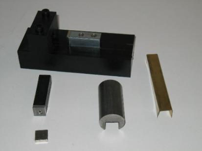 Secured
to the end of the piston is a piece of mild steel 1/2x1/2x1/8 inch in
size which is the same size as each of the two neodymium magnets
used. One of the magnets is in the foreground of the picture. It is
held on the piston by the attractive force to the steel piece. The
other magnet is held in the same way to the steel piece mounted in
the center of the platform. The cylinder in the middle of the picture
is the sleeve which is made of mild steel and a slot was milled in it
to fit over the piston and stationary steel piece. The part on the
right is a thin piece of brass used to provide a bearing surface and
maintain a small air gap between the sleeve, piston, and the
stationary steel piece. The cap head screws holding the platform
together are stainless steel (non magnetic). I used plastic for the
piston because it has less friction than if it were made from mild
steel.
Secured
to the end of the piston is a piece of mild steel 1/2x1/2x1/8 inch in
size which is the same size as each of the two neodymium magnets
used. One of the magnets is in the foreground of the picture. It is
held on the piston by the attractive force to the steel piece. The
other magnet is held in the same way to the steel piece mounted in
the center of the platform. The cylinder in the middle of the picture
is the sleeve which is made of mild steel and a slot was milled in it
to fit over the piston and stationary steel piece. The part on the
right is a thin piece of brass used to provide a bearing surface and
maintain a small air gap between the sleeve, piston, and the
stationary steel piece. The cap head screws holding the platform
together are stainless steel (non magnetic). I used plastic for the
piston because it has less friction than if it were made from mild
steel.
I'm using the following pictures
to help show how the pieces fit together and work.
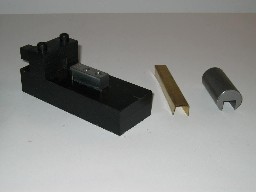 In
the picture to the left the magnet is placed on the piston and the
piston is placed in the slot on the platform. You can see the piston
is hanging out of the back of the platform, this is due to the
magnets repelling each other.
In
the picture to the left the magnet is placed on the piston and the
piston is placed in the slot on the platform. You can see the piston
is hanging out of the back of the platform, this is due to the
magnets repelling each other.
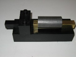
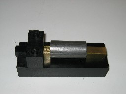
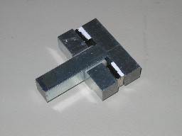
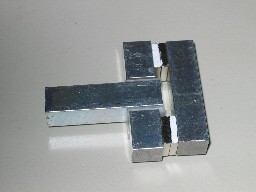
The
following pictures show the brass bushing and sleeve in place. In the
bottom left, the sleeve is in its retracted position allowing the
magnets to repel with the same force as without the sleeve. The
bottom right shows the sleeve extended to allow the piston to be
easily moved closer to the stationary magnet.
You
can see that the sleeve does not need to be extended very far to
cause the “short circuiting “ of the magnetic fields. I
actuate the device by moving the sleeve by hand and observing the
forces on the piston. With the sleeve extended, it requires a
relatively small amount of force to pull / slide the sleeve back to
cause the “open circuiting” and allow the magnets to
repel each other. The piston nearly shoots out of the platform. It
must be noted that for best performance the sleeve should be extended
only far enough to allow the piston to be moved close to the
stationary magnet. Otherwise, extending it further will cause the
piston to attract to the sleeve before the magnets start repelling
each other. If you build one of these for yourself, you will see what
I mean.
The
Figure 1 below shows the magnetic fields in “open circuit”
and “closed circuit” conditions.
Figure
1
Potential
Applications:
Reciprocating
Motor ( though I believe it would require large strong magnets in
order to produce torque that could be used to do work).
Linear
Actuator (maybe some kind of manually operated bolt action latch)
Magnetic
field summation and cancellation circuit:
This circuit shows how the
direction of magnetic fields can sum together to create a large
attractive force or can be alternated to cause cancellation and
create zero force. The circuit contains two permanent magnets and a
plunger, or piston, connected in parallel. An air gap exists between
the plunger and the circuit members so that it works in the same way
as a plunger in a solenoid. When the magnets are mounted so that
their North and South poles are in the same direction, the magnetic
fields in the plunger are in the same direction and sum together to
create a force on the plunger with the strength of both magnets. When
the magnets are mounted so their North and South poles are in
opposite directions, the magnetic fields in the plunger are also in
opposite directions and the fields cancel each other creating zero
force on the plunger. Below are pictures of the test fixture I built
to try this out.
 The
picture on the left is an exploded view of the circuit. I used
white-out on the magnets to show which side is North pole. The
members of the circuit, and plunger, are made of mild steel square
stock 1/2x1/2in. that I got from the local hardware store. The
plastic piece in the middle acts as a guide for the plunger and
provides an air gap between the plunger and the two lower members of
the circuit. I made the plastic piece out of delrin, since I have
some delrin scraps, but you could probably find a part at a hardware
store that will work after a little modification.
The
picture on the left is an exploded view of the circuit. I used
white-out on the magnets to show which side is North pole. The
members of the circuit, and plunger, are made of mild steel square
stock 1/2x1/2in. that I got from the local hardware store. The
plastic piece in the middle acts as a guide for the plunger and
provides an air gap between the plunger and the two lower members of
the circuit. I made the plastic piece out of delrin, since I have
some delrin scraps, but you could probably find a part at a hardware
store that will work after a little modification.
Below
are pictures of the circuit assembled in the two configurations. On
the left, the magnets have their North poles in the same direction
and the plunger is attracted to the top member. The right picture has
the magnets mounted so their North poles are in opposite directions
and the plunger has zero force on it within the air gap region in the
middle of the circuit.
The Figure 2 below shows the
behavior of the magnetic fields in both cases.
Figure 2
I am postulating, contrary to
popular belief, that in case 2 the magnetic fields do not “link”
with each other but form their normal loops and cancel each other in
the plunger in the region of the air gap as shown. I hope to obtain a
gauss meter to take measurements and prove or disprove this theory.
Potential Applications:
This could be used for motoring
but would be most impressive in a generator application.
Discussion
of known phenomena and their potential applications (food for
thought):
In
a magnetic circuit with permanent magnets, the total flux is
constant, thus the flux density in a region of the circuit can be
increased or decreased by changing the cross sectional area in that
region. If the circuit is used to apply force on an armature there
must be at least two air gaps to allow movement of the armature (or
could be called a plunger as in a solenoid) and the forces on the
armature can be altered by changing the area and/or width of the air
gaps. There are two types of forces acting in these air gaps, a
normal force and a shear force. The normal force acts in-line with
the magnetic field (like the plunger in a solenoid) and the shear
force is tangent to the alignment of the magnetic field ( like the
armature of an electric motor). I believe there could be a way to
create a magnetic windmill affect using a combination of different
sized air gap areas and widths. This is easier said than done, but I
think it is possible. The first example in Figure 3 below shows how
the normal force is affected by changing the area of the air gaps.
This
is Example 4.4.1 in Furlani, Ref (1), which has been modified to have
two air gaps with different size areas.
 PM
is the permanent magnet and Am is the cross sectional area of PM. The
lm is the mean length of the magnetic path and the + x is the
convention chosen for positive x direction. We assume the magnetic
circuit material has large Um and is not saturated and there is no
fringing at the air gaps. Also, we are ignoring the gravitational
forces on the armature.
PM
is the permanent magnet and Am is the cross sectional area of PM. The
lm is the mean length of the magnetic path and the + x is the
convention chosen for positive x direction. We assume the magnetic
circuit material has large Um and is not saturated and there is no
fringing at the air gaps. Also, we are ignoring the gravitational
forces on the armature.
Figure
3
Here
we derive the equations for the flux density in each air gap and the
force acting on each side of the armature. From equation (8) below,
if the air gap lengths x and y are equal the net force on the
armature is in the – x direction, F2 > F1, since A1 > A2.
If we make the air gap lengths equal and change only the air gap
areas, the change in force to change in areas is linear and less than
one-to-one. For instance, if A1 = 5(A2), then F2 = 2.69(F1). Bummer,
but still may be useful. The relationship of the forces with respect
to air gap length is non-linear second order (square in the
denominator). So, for the areas in the instance above, we would have
to move the armature in the positive x direction by a factor of 1.63
to make F1 = F2 and F = 0. This would be a relatively small change in
air gap lengths.
The
magnetic shear force is the force that produces the torque on the
rotor of an electric motor and in some cases is the force that moves
the armature of linear actuators. The Figures 4(a), 4(b) and
equations below are from Example 5.8.1 in Furlani, Ref (1), and are
shown here for clarification purposes. The equations are derived
using the energy approach.
Figure
4(a)
Figure 4(b)
The
example uses an N turn coil in place of a permanent magnet, however,
the force characteristics do not depend on the source of the magnetic
field. Here, the energy in the magnetic field, equation (1), is
expressed as a function of flux linkage, lambda, and the inductance
with respect to position along x direction. We then derive an
expression for the inductance, L(x). From this, we are able to derive
an expression for the force F.
Equation
(6) shows that F increases as x approaches d. In an actual circuit
like in Fig 4(a), F would reach a maximum at about x = d and would
then decrease as x > d. Also not shown in these equations is that
F goes to zero when the armature is fully in the air gap and x <
0, and F becomes positive when the armature begins to exit the air
gap in the negative x direction.
Equation
(7) shows that the magnitude of F is directly proportional to the
width, w, of the armature. This characteristic could be used to
manipulate the forces on an armature as it enters and exits an air
gap.
So
here is some useful information about magnetic circuits. Have fun
experimenting!
References:
(1)
Edward P. Furlani (2001). “Permanent Magnet and
Electromechanical Devices”, San Diego, CA: Academic Press.
Please
send questions and comments to: myers@ultrasw.com