The Electric Version of the Gasoline Engine
Now you can have the performance and tune-ability of a gasoline engine AND go emission free electric with more range!
The Series Resonant Driver (SRD) motor system is a new concept of driving Switched Reluctance Motors (SRM) for electric vehicles, and similar applications. With the SRD system, the motor has output power characteristics similar to an internal combustion engine and draws 2 times less current than the same SRM with conventional driver. Unlike conventional electric motor systems, the SRD is designed to provide the performance and tune-ability similar to that of an internal combustion engine AND provide extended battery range using the same battery pack. As mentioned on the home page, this system takes advantage of the inductive properties of the SRM where the phase inductance is used as the inductor of a series resonant circuit. After the “half period” through a phase, the system needs only to replace the switching and copper losses of the circuit onto the charged capacitor, and to raise or lower it's energy level according to throttle position. At constant throttle, the system needs only to “top-off” the charged capacitor of the series resonant circuit to replace the energy lost from the electronic components, which is a fraction of the energy that went through the motor phase during a half-period. For a more complete discussion of the system, skip down to the section of "how it works". A prototype SRD system has been constructed using a single phase switched reluctance motor and integrated onto a racing kart chassis (see below).
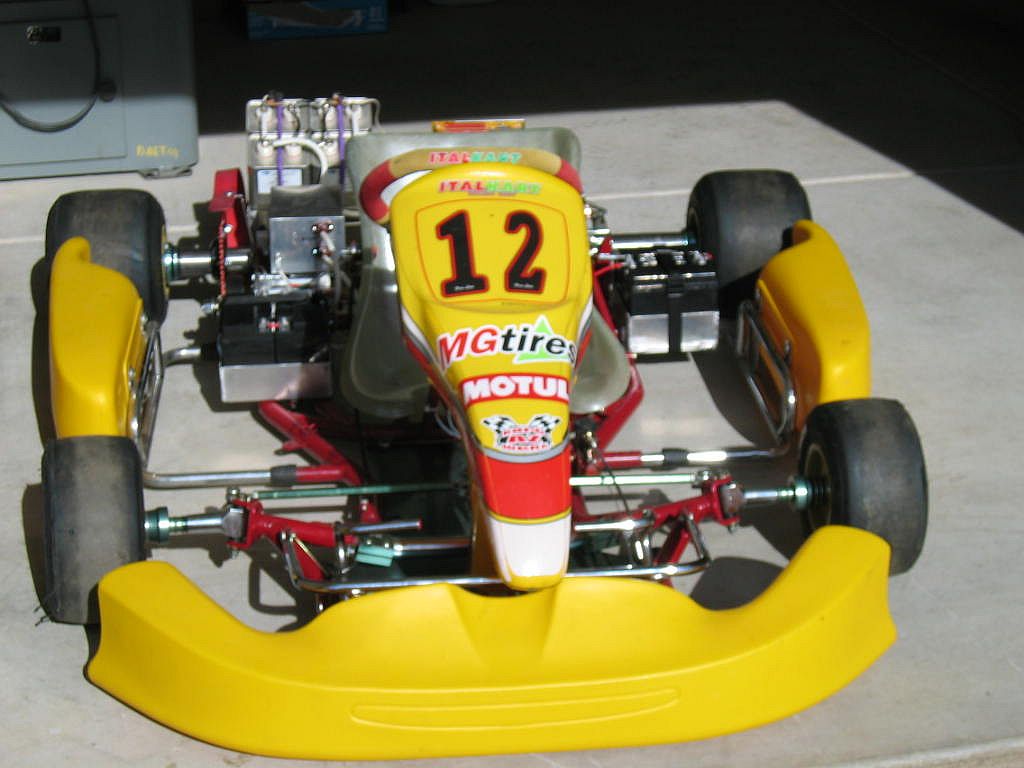
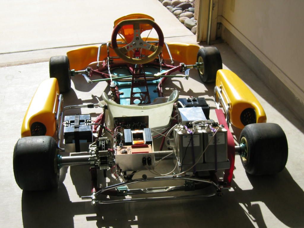
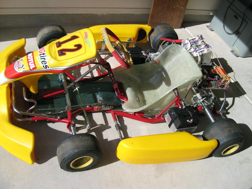
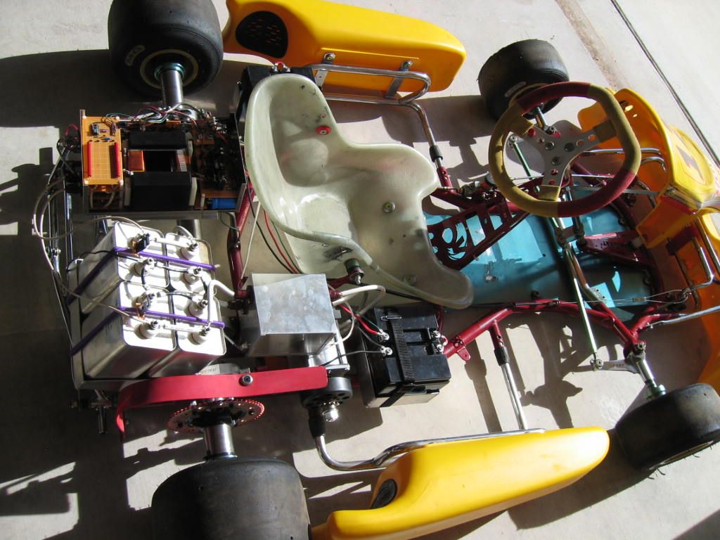
The KiloVolt Kart prototype.
The kart is powered by four 12V, 10Ahr motorcycle batteries connected in series to make 48V input. The capacitors will be charged to 500V at idle and up to 2000V at full throttle.
Current Status:
This project is on hold until the new DC-DC converter is designed. I am presently spending my efforts on the SRM high-efficiency controller design for the self-sustaining generator since that controller can be used to replace OEM controllers in products that use SRMs. The following paragraphs discuss the SRD system status to where I put it on hold.
At this time, the SRD system runs, however, the faulty converter is preventing me from driving the kart as it gets hot and then does not produce high enough output voltage to accelerate the kart. When the converter gets hot (which only takes a few seconds) the output voltage maxes out at only 850VDC which is just enough to engage the clutch and start to move the kart. If you gave the kart a push, the motor system would keep it moving on level ground. I don't want to demonstrate the system working this poorly.
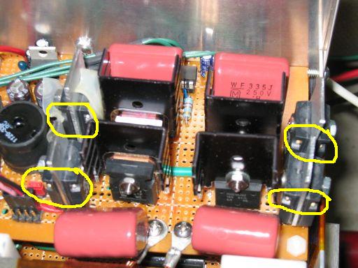
The DC-DC converter must be redesigned to include a more “proper” implementation. The current design keeps burning up snubber resistors. I have 200W resistors on it now and they have their guts nearly blown out (yellow circled in the picture above). It appears they are taking between 100W and 150W average power, just enough to degrade the resistors but not totally burn them up. This is due to two problems; the limited board size prevents proper heat sinking of the snubbers, and the excess power in the snubbers is caused by harmonics induced between the snubbers and the input filter (and the low switching frequency of 12KHz makes the problem worse). Since higher wattage resistors would be too large and expensive for this design, I am forced to work on a new converter design.
I have designed and simulated a new DC-DC converter. It will use the phase shifted switching method and have a switching frequency of 75KHz to 80KHz which will reduce the transformer size (by factor of 6) and eliminate the need for snubbers. However, the battery technology is changing and this greatly affects the converter design. The newer electric motorcycles and karts are using battery packs with voltages of 72V and up to 96V. Using a higher voltage battery pack helps make my converter job easier and more efficient (could get 90+%). I should plan on using the higher voltage battery packs.
Other than the DC-DC converter, the system seems to be operating good. We made changes to the system controller logic and power SCR gate trigger circuitry which helped motor performance. We need to add more logic to the system controller and since the CPLD is nearly maxed out in usage of macro cells, I have decided to use an ARM7 for the system controller upgrade. The ARM7 meets the size, memory, speed, and I/O requirements for the upgrade. Project on hold pending upgrades and finances.
About the SRD system
Why Is The SRD Better?
Conventional electric motor systems “drive” the motor using electric energy straight from the battery. The conventional systems are not “tunable” once they are in the vehicle, the only way to change the performance of the system is to replace it with a bigger more powerful motor and battery, and even then the torque and RPM characteristics stay the same and are not changeable.
The SRDs efficiency is due to the “Series Resonant” part of the system which allows the capacitors to drive the motor and the battery is needed only to replace the charge losses in driving the motor. The SRD system can be adjusted to provide different torque and RPM characteristics by changing the timing of the capacitor discharge and the duration of the charge period through software parameters. Thus, it can be “tuned” similar to how a hot rodder tunes a gasoline engine for better performance. Also, the SRD can gain more power by upgrading the systems DC-DC converter only and adjusting software parameters.
Since the SRD is not a conventional electric motor system, it is not useful in conventional electric motor “actuation” applications such as wheel chairs, automated machines, and robotics where the motor must be controlled to start, stop, and reverse quickly. The SRDs similarities to a conventional system are that of the AC fan motors and pump motors that turn on and spin only in one direction. However, the SRD can be designed to reverse direction in order to provide reverse drive for an electric vehicle, but that is not feasible at this time in development of the SRD.
The SRD system is patented, number 7215097, issued 5/8/07.
How it works:
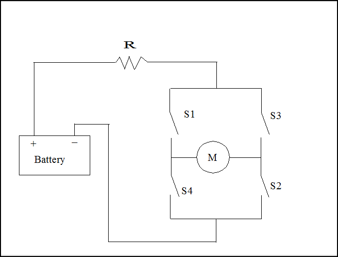
First, I must describe how a DC electric motor is driven by a conventional system. A diagram of the typical DC electric motor driver is shown in Figure 1 below. To drive the motor, the switches S1 and S2 are closed to energize a phase winding which causes the motor to “step”, or rotate, through part of a full rotation. Then, switches S1 and S2 are opened and S3 and S4 are closed to cause the motor to complete a full rotation. The switches S3 and S4 are then opened and S1 and S2 are closed and this sequence is repeated in order to cause the motor to rotate continuously. As you can see, when the switches close, the motor is powered directly from the battery. The resistor R is there to limit current and is usually a small resistance value.
Figure 1: Conventional motor commutation circuit.
A diagram of the SRD system is shown in Figures 2 through 6 below. As you will see in the following diagrams the SRD performs a switching sequence similar to that of the conventional system in Figure1, however, for the single phase SRM, there is a period where the motor is not energized and it must rely on its inertial energy for the rotor to rotate to the next position where the motor can be energized again in order to maintain continuous rotation. Let's begin the SRDs sequence with Figure 2 where the motor is spinning and capacitor C1 is at the end of its “top off”, or charge period. Here, energy has been converted from a low voltage charge on the battery to a higher voltage charge on C1. Switch S3 will be opened as soon as the charging period for C1 is complete. Capacitor C2 is empty of charge. When S1 and S2 are closed, the charge on C1 will flow through the motor and into C2, minus the losses incurred in going through the motor. You'll see this in the following figures.
The red fill in the capacitors represents the voltage level, or charge, on the capacitors and the red lines indicate the flow of charge, or current (ib = battery current, ic = charge current, and id = discharge current).
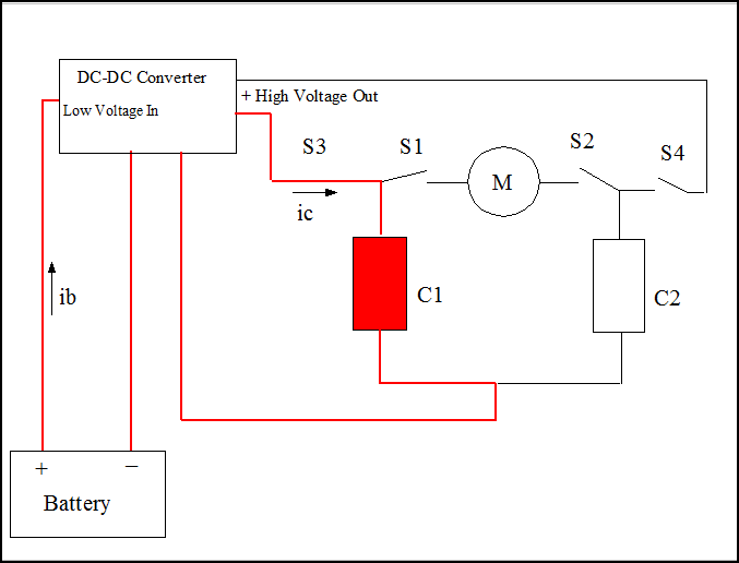
Figure 2: End of capacitor Top-Off sequence.
With the motor continuing to rotate and C1 charged up, S3 is opened and the system waits for the rotor reach the position where the motor can be energized. Figure 3 shows the condition where the motor is energized (I call it the fire position) and the switches S1 and S2 have just been closed and C1 starts discharging through the motor and charge goes into C2. This is similar to the switching sequence of S1 and S2 in the conventional system in Figure 1. The main difference is the energy is coming from the capacitor and not the battery.
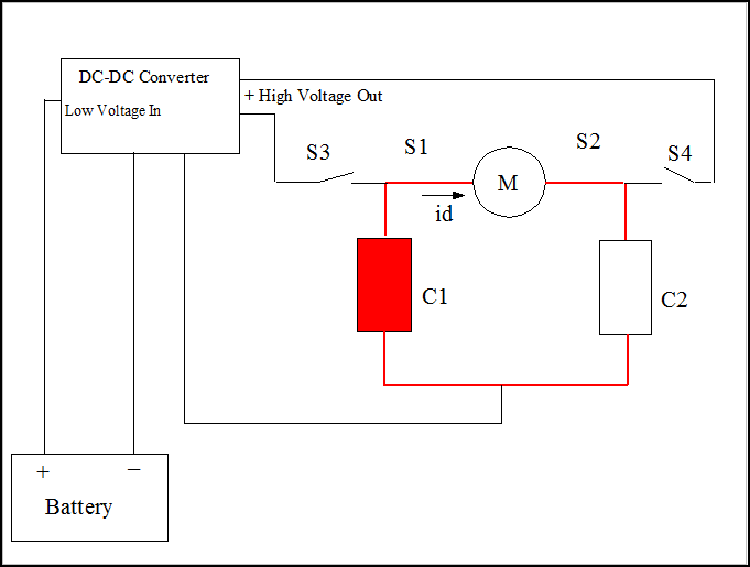
Figure 3: C1 discharges through motor phase inductance into C2 for one half period.
In Figure 4, the discharge of C1 through the motor to C2 has completed and switches S1 and S2 are opened to prevent C2 from discharging back to C1. We'll do that later. Now, C2 has a charge on it that is slightly less than originally on C1, and C1 is empty of charge (discharged). Switch S4 is closed to start the “top off” (charging) of C2 to get it to the same charge that C1 started with. The motor continues rotating while C2 is being charged. Note; the switches S1 and S2 are not allowed to close during the charging of C2 or C1.
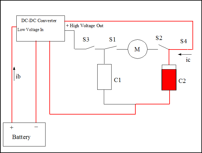
Figure 4: Half period from C1 to C2 complete, the system now Tops-Off C2.
When C2 is charged the system waits for the motor to reach the next fire position. Then switches S1 and S2 are closed, as shown in Figure 5, to allow charge to flow from C2 through the motor back to C1. This switch sequence is similar to the conventional system when switches S3 and S4 of Figure 1 are closed to cause the motor to complete one rotation.
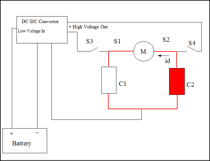
Figure 5: C2 discharges through the motor phase into C1 for one half period.
Finally, the charge from C2 has gone through the motor and back into C1, as shown in Figure 6, and we open switches S1 and S2 to prevent C1 from discharging back to C2. Also, we close switch S3 and begin charging C1. When the motor reaches the next fire position the motor will have completed one revolution and we start the whole process again from Figure 2.
Figure 6: Half period from C2 to C1 completed, the system now Tops-Off C1.
To Summarize: The Battery is used to top off the capacitors. The Capacitors are used to drive the motor.
Ok, you made it this far so let's discuss the “Series Resonant” part of the system. With switches S1 and S2 closed, and S3 and S4 opened, the two capacitors and the motor form an oscillator circuit that oscillates electric charge back and forth between the two capacitors through the inductance of the motor. This oscillator circuit behaves the same way as the spring and mass system that you may be familiar with as shown in Figure 7 below. If you were to pull the mass M down to X1 and let go, it would bounce up and down between X1 and X2 until it finally stops and comes back to rest at X0. This bouncing is an oscillator and would continue oscillating if there were no air resistance or resistance in the springs material. An electric circuit with a capacitor and inductor will oscillate in the same way.
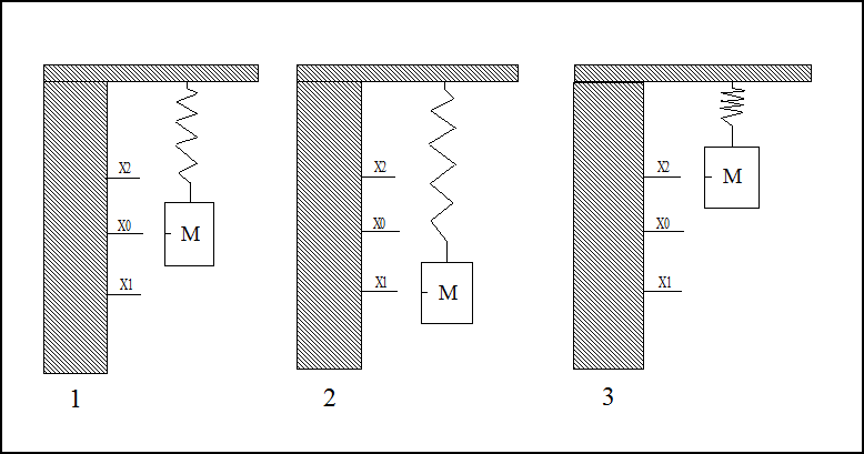
Figure 7: Spring and mass oscillation example.
The electric version of the spring and mass system is shown in Figure 8 where the capacitors C1 and C2 behave like the spring and the inductor L behaves like the mass (and momentum). Here we are oscillating electric charge between C1 and C2, and current “i” is the velocity and direction in which charge is moving. At T0, C1 is initially charged, C2 is uncharged, and S1 is open which is like pulling down the mass in part 2 of Figure 7. Then closing S1 lets the charge start flowing through L into C2 (lets the mass go) and the charge oscillates as shown in the clockwise sequence T1 through T4 and repeats at T1. Like the spring mass system, the electric charge oscillations will eventually stop due to resistance.
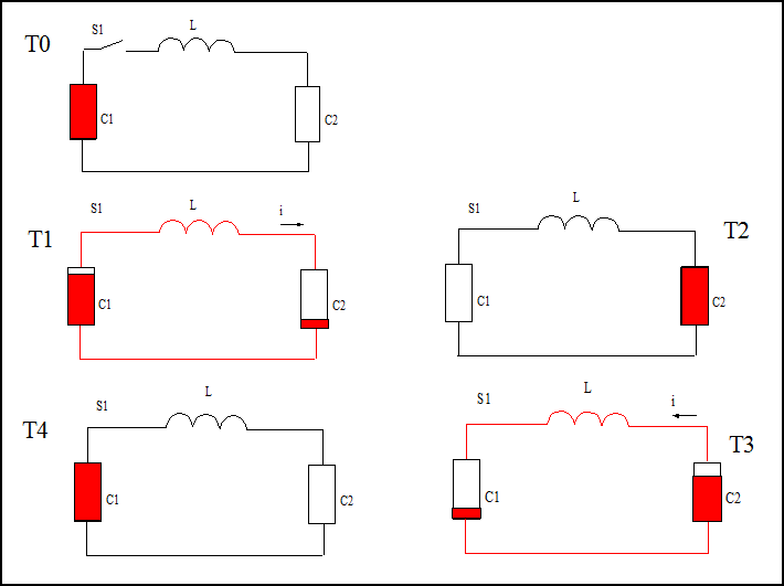
Figure 8: Oscillation in ideal series resonant circuit.
As a qualitative description, the inductor L (physically a coil of wire) acts like mass and momentum which is the “mass in motion remains in motion until acted on by another force”. The voltage on C1 provides force to move charge through L which is represented as current i moving in the direction of the arrow. Once charge is moving through L the charge continues moving until a force acts to stop it. This stopping force occurs when C2 becomes charged to the voltage that C1 had initially. Once C2 is charged and the current stops, the charge will oscillate in the opposite direction back to C1. Also, like the spring mass system, this circuit oscillates at a natural, or Resonant, frequency which is determined by the values of C1, C2, and L. The Resonant frequency is not affected by the voltages and currents in the circuit. Since the capacitors and inductor are connected in Series, the circuit forms a Series Resonant oscillator circuit.
Note to Engineers: when a series resonant circuit is in resonance, the inductive impedance Xl and capacitive impedance Xc are equal and out of phase by 90 degrees so that they cancel. Consider the following equations (taken from Wikipedia “LC circuit”);
In the SRD system with a switched reluctance motor, the inductance of the phase winding is an average of the inductance as the rotor poles move from unaligned to aligned position with the stator poles. Thus, the instantaneous resonant frequency changes as the rotor poles move to align with the stator poles. The changing inductance creates a back-emf as the motor speed increases which causes the energy needed to top-off the capacitors to increase. The values of the capacitors and phase inductances can be chosen to achieve a desired rated motor speed and retain the over-unity COP.
Below is an animation of the system to illustrate the capacitor discharging and charging sequences in the SRD. The coils in the motor are the inductor L of the circuit. The switches S1 and S2 are implemented using solid state switches which are- diodes and Silicone Controlled Rectifiers (SCRs). The SCRs act to close the switches and the diodes act to open the switches. The switches S3 and S4 are integrated into the DC-DC Converter.
SRD Motor System Operating Sequence
When the motor coils are red, a magnetic field is created and the rotor poles are being attracted to the poles of the coils. When the motor coils are black there is no magnetic field and the rotor is “free wheeling”. The motor pole sizes are not actual sizes, they were drawn this way to provide clarity.
Prototype Design and Fabrication:
The prototype described here is version 2. The first version was smaller and was more of a proof of concept / experiment to justify continuing development of this system. The first version would start up and run for only about one second which was a result of two problems; 1) the DC-DC converter was a flyback converter and did not provide enough output power to keep the capacitors charged up, and 2) it used commutator brushes to discharge the capacitors and had significant amount of arching when the brushes made contact and this greatly reduced the amount of energy that could be recovered (about 65% energy recovered). Version 2 uses a full bridge DC-DC converter with appropriate output power to charge the capacitors at the required rate, and uses high voltage Silicone Controlled Rectifiers (SCRs) in place of the commutator brushes. The SCRs are “hard fired” as is common in industry. By using the SCRs with “hard firing” the switching losses are greatly reduced (observed about 96% energy recovery). The following paragraphs discuss the design and construction of the version 2 prototype.
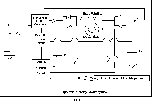
Figure 1 is a simplified diagram of the SRD motor system. The capacitors will be charged to a voltage ranging from about 500V, at idle, to 2000V at full throttle. I expect this prototype to have the performance equivalent to a good running 50cc two stroke gasoline engine with 3 to 5 HP. I chose to integrate the prototype SRD into a go-kart chassis due to its ease of access to the motor system. Ultimately, I would like to integrate the system into motorcycle and motor-scooter (like the Vespas) chassis.
 The
prototype uses four 12V, 10Ahr motorcycle batteries connected in
series to provide a 48VDC source. The DC-DC converter is rated at
2KW, 2KV and has a full wave rectifier on the output with switching
circuitry to allow it to charge either of the two capacitors. The
motor is a single phase switched reluctance motor that I fabricated
for this prototype. The capacitors, C1 and C2, each consist of two
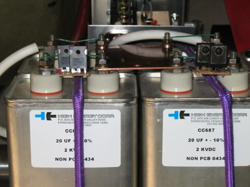
20uf capacitors connected in parallel to make 40uf. Each of the four
capacitors is an oil filled capacitor rated at 2KVDC.
The
prototype uses four 12V, 10Ahr motorcycle batteries connected in
series to provide a 48VDC source. The DC-DC converter is rated at
2KW, 2KV and has a full wave rectifier on the output with switching
circuitry to allow it to charge either of the two capacitors. The
motor is a single phase switched reluctance motor that I fabricated
for this prototype. The capacitors, C1 and C2, each consist of two
20uf capacitors connected in parallel to make 40uf. Each of the four
capacitors is an oil filled capacitor rated at 2KVDC.
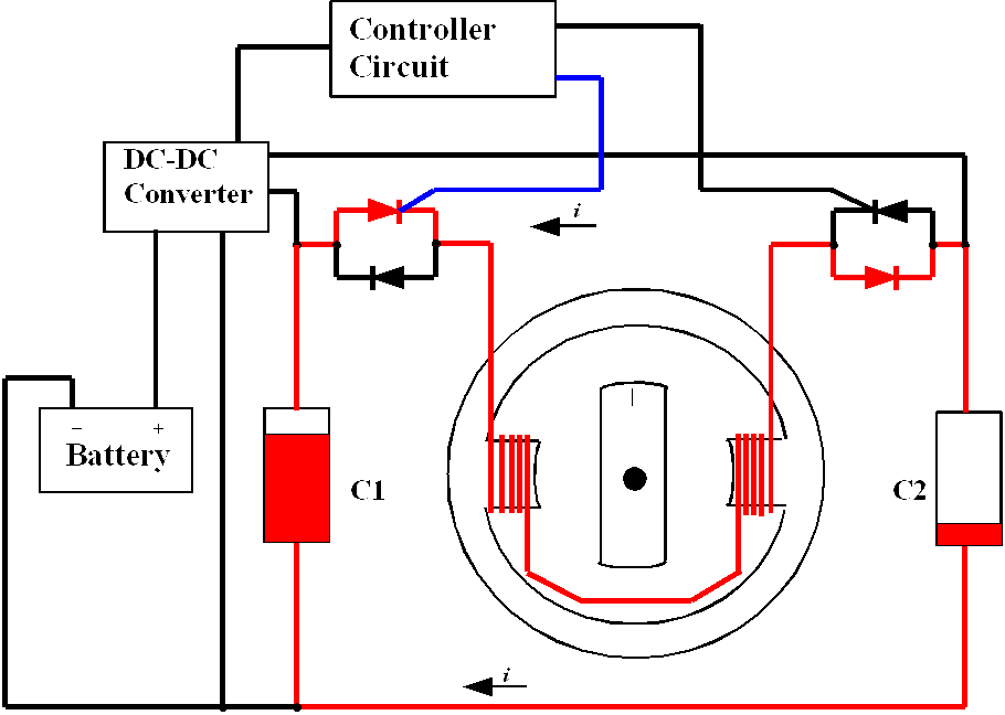
The inductance of the motor phase winding is 28mH in the aligned position and 5mH in the unaligned position. See the Switched Reluctance Motor Construction page for more detail. As you can see from FIG. 1 the switches are implemented using power diodes and SCRs and perform the switching as described at the top of the page. Also, in the figure is a box called Capacitor Drain Circuit. This circuit is used to drain the small amount of residual charge left on the capacitor after discharge in order to prevent charge build up and to create maximum potential difference between the charged and discharged capacitors. I have designed this circuit to send the “dumped” charge to a storage capacitor so it can be re-used by the system.
The Switch Control Circuit, or System Controller, is the brains of the system. It controls the voltage level the capacitors are charged to based on throttle position, and fires the appropriate SCR for the charged capacitor based on the Motor Shaft position sensor input. Also, the controller circuit will be designed to perform “fire when ready” of the SCRs which will wait for the capacitor to be charged to the commanded level before firing the SCR. This will allow the motor to be pulsed two times per revolution at low RPM and as soon as possible at high RPM. During acceleration, the appropriate capacitor is charged for 10ms directly after the discharge period which allows the capacitor(s) to be charged in steps of 500V until the commanded voltage is reached.
The links below will display a new page for that topic.
Switched Reluctance Motor Construction
This site will be updated as I make progress.
Please send comments and questions to: myers@ultrasw.com
If you have Javascript enabled you can use the button below, else use the back button in your browser.